| Author |
Message |
|
sidewinder
On the Road
Joined: Wed Aug 11, 2010 9:27 am
Posts: 621
Location: Sheffield
GTM: Libra
|
 Re: 1.8 vvc timing Removing the spare wheel, spare wheel moulding, battery and battery moulding will give good access to the ends of the tunnel pipes. Removing the front clam (unplug lights connector first!) is easy if you have two people to do it and gives much better access but isn't entirely necessary.
If you need to remove the big rad pipes I found withdrawing them rewards easiest. I lubricated the p clips holding them in the tunnel and twisted/pulled them out - the clips can twist causing em to jam so its best to have one pulling and one under the car. I did this rather than trying to remove clips cos i'd have to take seats/carpets out to get at their bolts. Threading the pipes back thru the clips was easier, especially if you lube them again first.
My big rad and small heater ally tunnel pipes are not beaded either, as rec'd from factory, but I use two jubilee clips per end and generally have no issue. All the bends/straights at the front and rear I replaced with silicone hose and proper beaded ally pipes.
_________________
2000 GTM Libra 1.8VVC 145BHP
|
| Mon Jun 10, 2019 11:04 am |
  |
 |
|
sanzomat
GTM Nirvana
Joined: Sun Oct 19, 2014 10:10 pm
Posts: 1138
Location: Bristol
GTM: Spyder
|
Re: 1.8 vvc timing In my experience you can get away without beaded ends if using rubber hose but silicone hoses slip even with two hose clips. As Sidewinder says, removing the battery box gives good access. I changed my radiator for the Passat one without taking the front clam off. Mine are beaded but I still get a very slow leak from the join on the front of one of the main ali pipes. It seems that there is a pin hole in the ali on the wrong side of the bead and the hose only just overlaps with it. Next time I have the coolant drained I'll change the hose as I have a set from a TF that are much longer so I can put the clips on past the pinhole. To be fair it hasn't got any worse in the last 3 years and only leaks a little bit. I've never seen it drip when the coolant is hot so I wonder if some expansion closes the hole and it doesn't seem to leak when its cold and un-pressurised, just a few drips as it cools down. Good luck!
|
| Mon Jun 10, 2019 1:49 pm |
|
|
|
tonygerrard(1049)
Part built GTM
Joined: Thu Nov 22, 2007 10:31 am
Posts: 132
|
Re: 1.8 vvc timing Great, thanks. The battery housing bolts are hard to get to behind the pedals but I found them so I'll look to remove the front clam and proceed as you say.
Few other generic questions:
Does anyone have a recommendation on a good air filter? Decent bang for buck, but not like £300! I currently have a cheap one off eBay, just to keep the dust out during commissioning, but it's not going to be great on the road.
On the wiring front the diagrams suggest a white + orange wire from the speed sensor should be connected to my speedo, but the ECU pin out's say the white and orange on red connector pin 30 is "not used." Does that mean the wire should run directly from the sensor to the speedo?
I may have made a mistake in that I purchased an oil temperature gauge and it appears that the metro loom only reported out engine oil pressure. Does the 1.8 VVC engine have an oil temperature sensor or is it just pressure? I see the VVC has an oil temperature sensor...?
|
| Sat Jun 15, 2019 4:46 pm |
|
|
|
sidewinder
On the Road
Joined: Wed Aug 11, 2010 9:27 am
Posts: 621
Location: Sheffield
GTM: Libra
|
Re: 1.8 vvc timing I made my battery holder fixings 'captive' in the tub and floor of the cowling for just this reason - thick pieces of stainless bolted in place that have threaded holes in em to accept the M6 battery molding fixings. I used to use just a KN RU-1480 filter clamped straight on the intake drawing air from inside engine bay for ages which seemed to work fine, but it did get quite dirty. Replaced it with a cheapo clone of the KN Apollo kit, ditched the actual filter element included in the kit and bought a genuine KN one (RC-5052) - worked out much cheaper than a whole genuine KN Apollo kit. Cold air is better and it looks 'cooler' - no real performance change I could tell, but hasn't made it worse so I like it. air-filter-t3945.html?hilit=apolloWhat instruments/speedo gauge do you have? The MGF (early) uses mechanical cable speedo drive direct to the instruments, later ones have electronic I think but both go direct to instruments - the ECU isn't involved. There is a speedo sensor available that's supposed to connect to the ECU but it's only for the automatic CVT(?) version. My VVC doesn't have oil temp gauge, only pressure warning light (though I do have a plug socket for it on the engine). The temp sensor goes in a blanked off hole in the oil filter mount I think. I think the ECU is again not involved but am not sure.
_________________
2000 GTM Libra 1.8VVC 145BHP
|
| Sat Jun 15, 2019 5:44 pm |
|
|
|
sanzomat
GTM Nirvana
Joined: Sun Oct 19, 2014 10:10 pm
Posts: 1138
Location: Bristol
GTM: Spyder
|
Re: 1.8 vvc timing Air filter - I'm using a simple K&N cone on the throttle body. Seems to work okay but I have thought about ducting in colder air one day.
Speedo - mine has a gismo that fits to the gearbox end that converts the mechanical speedo cable drive into an electronic signal for the GTM supplied speedo. IIRC the wire goes direct from the gismo to the speedo, not via the ECU but I could be wrong.
Oil temp - I fitted one of these to my current MGF VVC but there wasn't a spare tapping for the sender so I added a sandwich plate between the oil filter and housing. Mine doesn't seem to have an oil pressure light but does have a pressure gauge. The gauge sender is in the hole that would originally have had the switch for the light. I have a TF160 engine waiting to go in, the TF did have an oil temperature gauge (but not oil pressure, just a light), There is a tapping for the temp sender on the oil filter housing elbow thingy. That engine also has a factory fitted oil cooler in the form of an oil to water heat exchanger, kind of like a budget version of a laminover so I guess MG Rover realised that the oil does get a bit hot on these mid mounted k series.
My battery box top fixings are just tapped into the grp. Seems to work okay but if it ever comes too loose I might use rivnuts.
|
| Sat Jun 15, 2019 9:17 pm |
|
|
|
tonygerrard(1049)
Part built GTM
Joined: Thu Nov 22, 2007 10:31 am
Posts: 132
|
Re: 1.8 vvc timing I picked up some Smiths clocks ~4 years ago which were similar to the original GTM ones to fit in the original binnacle (my dad was lucky enough to buy one from Westfield). Pictures attached.
When it stops raining (if it ever stops raining!) I'll get on with the water and have a bash at wiring in the clocks. Fingers crossed the fuel sender / petrol gauge work because, for some crazy reason, no petrol gauge was installed on the car and I'm not sure if Dudley wired them up or not.
|
| Sun Jun 16, 2019 11:42 am |
|
|
|
sidewinder
On the Road
Joined: Wed Aug 11, 2010 9:27 am
Posts: 621
Location: Sheffield
GTM: Libra
|
Re: 1.8 vvc timing Did you get a speedo sender with the clocks? What's attached to the gearbox speedo drive at the moment? My gauges etc were American 'Classic Instruments' from a UK company, I got an 8 pulse electronic sender with em that I had to adapt to fit the GBox mech drive output. Might be some useful stuff for you here http://www.sidewinderforge.co.uk/netlib ... libra.htmlI think the sender I bought unnecessarily is the one for the MGF electronic speedo (YBE100520). Is there wires from the fuel sender under the dash somewhere?
_________________
2000 GTM Libra 1.8VVC 145BHP
|
| Sun Jun 16, 2019 2:58 pm |
|
|
|
tonygerrard(1049)
Part built GTM
Joined: Thu Nov 22, 2007 10:31 am
Posts: 132
|
Re: 1.8 vvc timing There were no adapters with the kit. The comments on the instructions (see attached) discusses three wire sensors, so I presumed it would be fine...
If anyone is familiar with the wiring and has any advise I plan to wire up as follows (metro loom unless otherwise stated):
Speedo to loom
Pin1: Green ==> Green (power supply)
Pin4: Red + White ==> Red + Orange (Instrument illumination / side light power)
Pin5: Black ==> Black (earth)
Pin6: White + Black ==> White + Orange (wire from the speed sensor on the PG1 gearbox)
Tacho to loom
Pin2: Red + White ==> Red + Orange (Instrument illumination / side light power)
Pin3: Red + Blue ==> White + Black (Tacho)
Pin5: Black ==> Black (earth)
Pin6: Green ==> Green (power supply)
I might have to move some of them depending on sensitivity as per the instructions, but won't know until I try them I suppose.
Not sure if I have missed something on the tacho - Pin1 (Brown + Slate) mentions "pull up for open collector ECU output" but I have no idea what that is!
On the loom there are two spare wires I have no connections for 1) Yellow + Green (throttle potentiometer) 2) I think was Black + Slate (not sure what this is for).
Attachments:
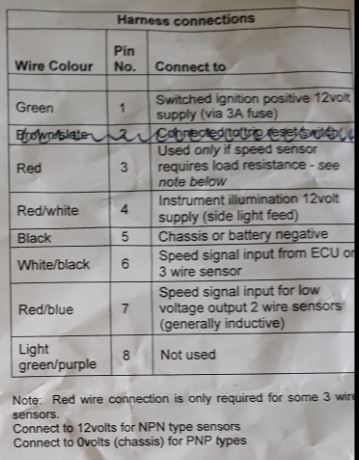 Speedo.JPG [ 38.8 KiB | Viewed 4938 times ]
 Tacho.JPG [ 62.25 KiB | Viewed 4938 times ]
|
| Mon Jun 17, 2019 3:00 pm |
|
|
|
tonygerrard(1049)
Part built GTM
Joined: Thu Nov 22, 2007 10:31 am
Posts: 132
|
Re: 1.8 vvc timing http://www.sidewinderforge.co.uk/netlib ... tmlb2.htmlWas a good link. I suspect my mystery Black + Slate might actually then be the Black + White for the brake fluid. I have got a fuel sender wire coming into the dash but I'm not sure if it's connected at the tank (fingers crossed). Looks like they had to mess with adding resistors to get it working properly. That sounds like fun  The gearbox speedo drive has a three wire sensor on top with, I think, the White + Orange wire coming out.
|
| Mon Jun 17, 2019 3:13 pm |
|
|
|
sidewinder
On the Road
Joined: Wed Aug 11, 2010 9:27 am
Posts: 621
Location: Sheffield
GTM: Libra
|
Re: 1.8 vvc timing The speedo should have little switches that you change to calibrate it to your setup - depends on wheel size ratios etc.
Found this online:
"You will need a speedo transducer (the part onto the top of the gearbox that converts the gearbox speedo into a digital signal. Then you need to supply power to it by taking a feed from the brown and pink (12v feed) wire from the ECU loom to the transducer*. Then take an orange a white wire from the transducer to the back of the clocks. I think the 3rd pin in the transducer plug is earth. Hey presto a working speedo!"
* I think basically you have a (ignition) switched 12v supply, an earth and a signal wire to the gauge.
Tacho - that pin 1 thing is something to do with what type of signal the ECU puts out, switched negative or switched positive I think(?). I would just leave it blank and see what happens & only concern yourself with it if the tach don't work. If you google "Tachometer pull up resistor" there's info. out there.
Yellow green, is this wire in the dash?
Black grey(prob white) comes from brake fluid level switch and should go to brake warning light. Should also be a grey/black coming from handbrake switch also goes to brake warning light.
Fuel sender has a wire going to earth point and the other goes to dashboard. So if you measure across that wire and earth you should get a resistance between 16 and 270 ohms (if the sender is working/connected).
_________________
2000 GTM Libra 1.8VVC 145BHP
|
| Mon Jun 17, 2019 5:02 pm |
|
|
|
tonygerrard(1049)
Part built GTM
Joined: Thu Nov 22, 2007 10:31 am
Posts: 132
|
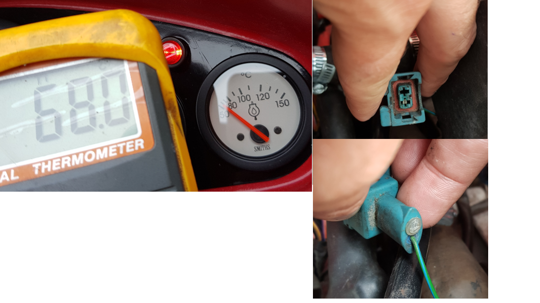
Re: 1.8 vvc timing We had a productive weekend sealing exhaust and water leaks and painted and replaced a lot of the interior and got the handbrake working - so we're getting close to an MOT I hope! We did have a problem with cooling. I suspect either the water pump or thermostat aren't working properly as the aluminium pipes around the head were hot, but the temperature of the tubes down stream of the stat and close to the radiator were cold. Will clean out the cooling system, replace the stat and water pump and see what happens. The tacho and fuel gauge worked without modification, so that's a bonus. Not had a chance to play with the speedo yet as I want to change the cambelt and water pump and get an MOT first. Saying that I'm under the impression a speedo must be fitted but doesn't necessarily have to work to pass an MOT...?  Having a few issues with the temperature gauges, (both oil and water), as both are inaccurate. The oil filter was ~70 C and the gauge only just moved, reading ~50 - 55 C. The water temperature sensor only has a single green + blue wire coming from it (which is correct on the wiring diagram - the "earth wire hole" is plugged with a plastic bung reinforcing this point) see photo attached. With a new sensor wired up and placed in a cup of hot water I could only get this temp sensor to work when an earth cable was attached to the other sensor pin. Grounding the brass shell did nothing (I thought it may be grounded through the block). I'll have to mod it so an earth wire is permanently attached, I guess. I put the tail of the sensor in hot water and compared it to the read out of a hand-held k-type thermocouple and I found the same (~15 C) difference. Perhaps these are just inaccurate sensors because they have poor heat conduction? I say that because when I accidentally dropped the whole sensor into the hot water the temperatures reported on gauge and thermocouple were actually pretty close!  I will contact speedy cables who supplied the gauges to see if they can recommend a way to calibrate them. There are two black wires in the back (I wonder if a resistor is supposed to be added here to increase the resistance to change the calibration?).
Attachments:
 Temperatures.png [ 892.39 KiB | Viewed 4825 times ]
|
| Thu Jul 04, 2019 6:55 pm |
|
|
|
tonygerrard(1049)
Part built GTM
Joined: Thu Nov 22, 2007 10:31 am
Posts: 132
|
Re: 1.8 vvc timing A few more measurements showing the temperatures to be quite different...
|
| Thu Jul 04, 2019 10:29 pm |
|
|
|
sidewinder
On the Road
Joined: Wed Aug 11, 2010 9:27 am
Posts: 621
Location: Sheffield
GTM: Libra
|
Re: 1.8 vvc timing Coolant is pumped around the heater circuit (smaller pipes) constantly, so you should have hot pipes front and rear and heat from the cabin heater blower once the engine warms up a bit. The heater matrix itself tends to be where air locks occur and can be a bit of a bugger to bleed to clear em. You'll only get hot coolant circulating to the rad circuit (big pipes) once the stat opens at about 97°C (pretty sure this is OE stat's temp). If the cooling system is running properly and free of air, once the engine is operating at temp you should get a very stable temp at the gauge and hot air from the heater whenever you select 'hot'. V important to have good stable cooling as otherwise can contribute to HGFs. A single wire for the gauge sensor is correct. Do you have an earth wire (coming out of the loom that passes there) attached to the rear face of your block? Make sure that and the earth to the starter are in good clean condition. Are the coolant sensors (ECU/gauge) you have original to the engine? ECU sensor should be brown or black and gauge sensor should be black or blue. They changed at some point and I think the output resistance range changed. https://forums.mg-rover.org/how-do-i-an ... rs-498585/
_________________
2000 GTM Libra 1.8VVC 145BHP
|
| Fri Jul 05, 2019 11:17 am |
|
|
|
Rich
Looking like a GTM
Joined: Mon Aug 18, 2014 6:07 pm
Posts: 169
Location: Devon
GTM: Libra
|
Re: 1.8 vvc timing Just on the cooling front, I have plumbed a Bosch auxiliary water pump into the heater circuit. It gives enough of a boost to keep the temperature under control and flush out the circuit when filling.
I had been having temperature problems when standing in traffic, this has fixed it nicely.
|
| Fri Jul 05, 2019 3:59 pm |
|
|
|
tonygerrard(1049)
Part built GTM
Joined: Thu Nov 22, 2007 10:31 am
Posts: 132
|
Re: 1.8 vvc timing I have a PRT thermostat underneath the recessed part of the petrol tank linked to the outlet of the head. Removed the original one to reduce risk of cooling shock on the HG. The bypass of the PRT runs to the heater, the pipe runs over the petrol tank. Turns out the stat was the wrong way around so I had to re-fit it and a number of pipes.
Have hot water coming out the bypass of the PRT towards the heater, but the heater blower and pipes under the clam do not get hot... Can't tell if the pipe is pinched above the tank or if there is an air lock. Only one of the heater pipes under the front clam has a bleed nipple, so I may cut the other one and install a "bleedable T piece" or a water pump as Rich suggests. The stat opens at 82 C and works well, but the rad fan didn't come on at 86 C (as per the metro manual). Fan tested using the battery and works. Perhaps the rad temp sensor is knackered, but I don't want to do any more testing until the oil and water temperature gauges are back in.
The sensors are original to the engine, the water is the blue type the ECU is brown type. I spoke with Speedy cables on Friday and they have offered to receive the 2x gauges and newly purchased oil and water temp sensors and they will calibrate them together so I get the most accurate readings. Win.
One other issue I'm having is that the charge light stays on when the car is running. I've tested and can see the alternator is charging the battery so I'm not sure why it's lit. I've read that some systems are supposed to use a diode, is that something anyone else has done?
|
| Sat Jul 06, 2019 10:38 pm |
|
|
